On my walk today I couldn't stop thinking about various x220 mods and I feel like I need to get them down on paper.
I think the expresscard / NVMe card mod is cool, but I should just buy the SATA SSD I have my eye on and use that for a speed boost. NVMe can come later as a bonus or something, IDK.
Instead, I should build a series of increasingly complicated expresscard PCBs. We can start with one that has a 3.3V boost and exposes a USB-C port. I can desolder the connector from one of the devices I ordered.
Next I could try adding a USB hub, so I could have 2 ports and maybe an ESP32 or a pico or something else?
I could also do a variant that includes the NVMe drive and one USB-C port.
I think it would be neat to have a LoRa chip, or an RTL-SDR built in as well, but that seems a lot harder... Or I could use the [sparkfun micromod](https://www.sparkfun.com/micromod)! Put whatever processor I want inside a carrier and expose a stemma port? [good design docs from sparkfun](https://learn.sparkfun.com/tutorials/designing-with-micromod)
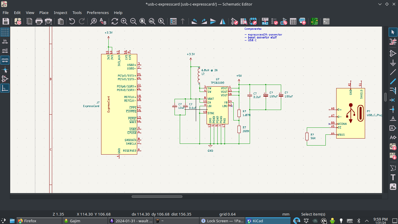
Gonna start on the PCB layout now actually. KiCAD already has an expresscard connector (weird), and USB-C. Now to read up on the circuit in the PowerBoost 500 from Adafruit: https://learn.adafruit.com/adafruit-powerboost/downloads

Idle thought: could maybe hook up a USB-PD thing? But no, I probably can't source enough current at 3V3 to make it worthwhile
Reading about the [TPS61090](https://www.ti.com/lit/ds/symlink/tps61090.pdf?ts=1706681751834) boost convertor so I can step up 3.3V to 5V for the USB to work properly. Some questions I have
- Can I leave the Low Battery Output (LBO) pin disconnected? yes, but tie LBI to ground
- What do I need to set FB to?
- What do I need to do with SYNC? Tie it to ground
I probably need to set connect LBI to the battery to avoid weirdness
Setting SYNC low will enable power save mode, which is what Adafruit does and I'll stick with that. I don't think I can / want to sink more current.
Although maybe it would be nice to have 1A output and I should look at the [TPS61030](https://www.ti.com/product/TPS61030) instead. Only question is if I need a bigger inductor?
On LBI/LBO from the docs:
> If the low-battery detection circuit is not used, the LBI pin should be connected to GND (or to VBAT) and the LBO pin can be left unconnected. Do not let the LBI pin float
On FB. I think Adafruit pulls the voltage a bit high, and they do this by using a 200K and a 1.87M resistor to make a little voltage divider. The datasheet (10.2.1.2.1) has similar values, although they have 1.8M for the other resistor.
Now they have an awful lot of capacitors, which I guess is important for power shit...
I don't get PGND
> Both grounds must be connected on the PCB at only one point close to the GND pin
Adafruit has a note about doing that as well, we'll see when we get to layout if it still matters.
On to the USB-C connector there's 2 pins I need to figure out: VCONN and CC
VCONN sounds like it's used for special cables. It's not required for my use case because I can't source 3A or do anything else fancy like PD. There's supposed to be a resistor on CC (56K) but a lot of the stuff is about being a device, not a source like what I'm doing.
https://microchipdeveloper.com/xwiki/bin/view/applications/usb/typec-features/cc-vconn-signals/
https://microchip.my.site.com/s/article/USB-Type-C-VCONN-Requirements
https://hackaday.com/2023/01/04/all-about-usb-c-resistors-and-emarkers/
There's also something confusing about CC and VCONN being flipped depending on the orientation, so maybe I need 2 resistors? Something for tomorrow