Ok, so reading through this [Hackaday article](https://hackaday.com/2023/01/04/all-about-usb-c-resistors-and-emarkers/), I think I am making a 'source' and thus need a pull up... But reading about how vconn works has left me more confused. I should look up an actual USB-C receptacle before I go further because I thought you couldn't know which is vconn and which is CC (since they are CC1 and CC2, but swap depending on the cable?)
I am building a Downstream Facing Port (DFP) by my read of [this TI Primer onf USB-C](https://www.ti.com/lit/wp/slyy109b/slyy109b.pdf?ts=1706763564538&ref_url=https%253A%252F%252Fwww.google.com%252F) , and I'm making a Source.
Oh damn, a Proper USB-C device checks for a CC connection of appropriate value and THEN enables power, which is to prevent problems if you plug 2 laptops together or 2 battery banks. Probably worth implementing but it does mean another chip probably. TI conveniently tells me they have these...
Alright, so my current understanding is that if I want to do it right, I need to have 2 independent pull up resistors on CC1 and CC2. If the voltage drops (because a sink has been plugged in and connected a pull down), I should enable VBUS at 5V.
The value of the resistors will control how much current the sink should expect. I think I should default to the 500mA of the standard, or the common 1A. 1.5A and 3A are part of the spec, but I don't think I can source those.
I will need to possibly pick a new footprint for the USB-C connector, since the current one is confusing to me, I don't think the receptacle can know which is VCONN and which is CC.
https://www.digikey.ca/en/products/detail/gct/USB4520-03-0-A/15283199
This looks interesting. It's cheap, it's "mid mount"
https://www.digikey.ca/en/products/detail/molex/2169900003/13913753 has a nicer footprint and I have heard of molex before so I think I can trust them
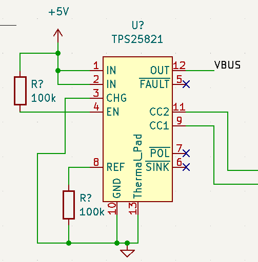
Ok, so I found that TI sells a chip that does exactly what I need: [TPS25821](https://www.ti.com/lit/ds/symlink/tps25820.pdf?ts=1706772270382). It's cheap on digikey and the footprint looks manageable. Basically it takes care of reading CC1 / CC2 and then enabling / disabling VBUS based on what it finds. I can also get a sister chip that does the VCONN stuff, but I think I'll Keep It Simple.
Also [microchip UTC2000](https://ww1.microchip.com/downloads/aemDocuments/documents/OTH/ProductDocuments/DataSheets/UTC2000DS00001957C.pdf) looks interesting, but seems more complex
Ok, that's all wired up now
On to the USB-C port!
I need to see what to do with SBU1 and SBU2, and what to do with the 2 pairs of D+ and D-.
For SBU1 and SBU2 [this stackoverflow](https://electronics.stackexchange.com/questions/588126/are-usb-type-c-pull-resistor-neccesary-on-cc-and-sbu-pins) says to leave them disconnected. The same is done in a [reference design for the TPS chip](https://www.ti.com/lit/df/tidrue5/tidrue5.pdf?ts=1706833556132&ref_url=https%253A%252F%252Fwww.ti.com%252Fproduct%252FTPS25821).
That schematic also has both D+ and D- pairs wired together.